Making a Rose Engine Lathe
The lathes below are shown in order of popularity based on commentary from users with whom I have spoken. These are some very good options to give you some ideas. In a related note, I've catalogued some lessons learnt from making a cutting frame.

MDF Rose Engine Lathe 2.0
MDF Rose Engine Lathe
The MDF Rose Engine Lathe is oftentimes how people get started in this craft / hobby. This machine may look pretty basic, but don't be fooled. There are some very awesome aspects to this machine.
|
Advantages |
Disadvantages |
|
|
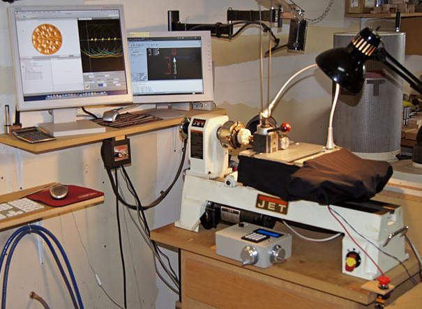
COrnLathe™
Image courtesy Bill Ooms
Computer-Assisted Ornamental Lathe
There are two ornamental turning artists who are at the leading edge of driving the craft forward with the use of computer assistance : Bill Ooms and Dewey Garrett. Both live in the Prescott, Arizona area.
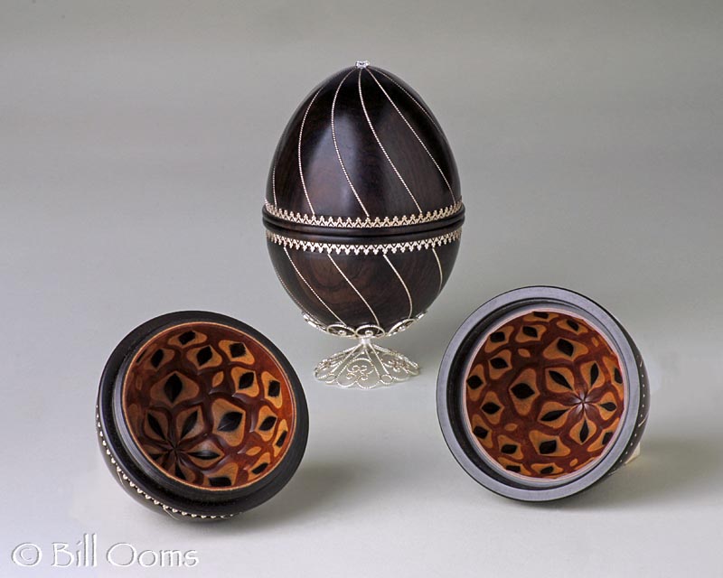  |
Bill Ooms is an accomplished artist who has created great works. The piece that I consider to be his most beautiful is shown to the left (he was very kind to share it).
The August 2014 edition of "American Woodturner", Vol 29, #4, has a great article about Dewey Garrett and his art.
In my correspondence with Bill and Dewey, both have stated that they prefer the term "computer-assisted" over "CNC". Their reasoning is that the use of a computer to help the artist achieve his goal is quite different from the typical use of computer numerical control (CNC), especially as CNC is identified with the repeated production of given object, not one-off artistic work.
Dewey Garrett published these videos showing the use of his custom-built LinuxCNC-driven lathe in use. Dewey does masterful work, and these are great examples of his lathe in action.
Bill Ooms documented the building of his Computerized ORNamental Lathe (COrnLathe™) on his web site. That site has a load of great information, and I won't take the time to repeat it here as Bill has done such a great job. Bill is to be greatly commended for freely sharing three things :
- the COrnLathe "hardware" designs he has created,
- the software he has created, and
- the designs he has created for ornamental cutting frames.
Some additional information is available about this machine on the Rose Engine Approaches page.
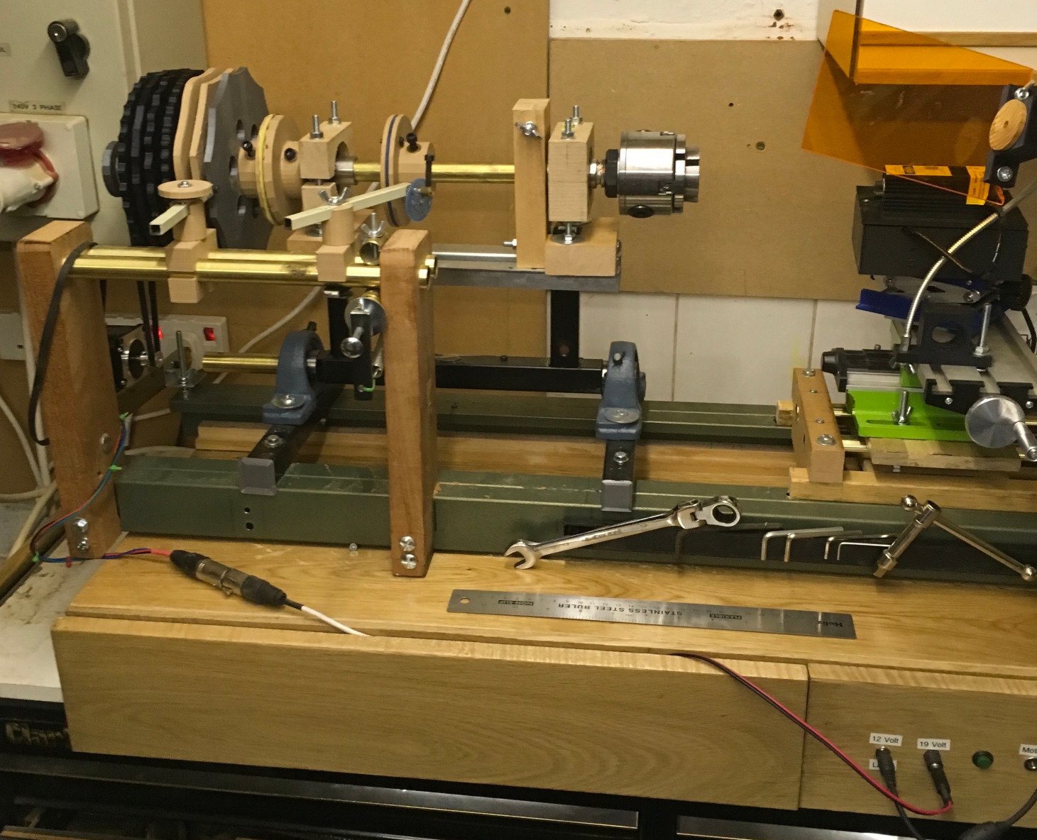
Very economic Rose Engine using parts
taken from an old bedstead
Image courtesy Adrian Jacobs
A "very economic rose engine using parts taken from an old bedstead"
Adrian Jacobs built his own rose engine lathe using parts from "an old bedstead". His notes about doing that process are below. Whist these instructions are not detailed enough to be followed, they show how much fun you can have just building a machine (if that is something you like). And, it shows a really cool use of the rose engine lathe with a laser for engraving.
- The process of building the machine was long and protracted because I was forever redesigning it. Each time I though that I had finished, I thought of a new idea to improve it - clear evidence to support Darwin's theory of evolution!
- The machine started out as a manually driven machine with a complex pulley system but when I came across Gary Liming's work on YouTube it was clear that stepper motors were a better option especially as they can be used to any indexing work to a high degree of accuracy using electronics.
- I had to build in a clutch mechanism between the rosettes and the main drive shaft so that I could do phased work. This also required a simple friction brake on the main shaft. When this was installed, phasing became very simple and extremely flexible.
- Fine tuning the machine remains a bit of a problem. Rubbers seem to work best when presented at the midline of the rosette but I still have some problems with too rapid fall off from step angles on rosettes. It is also clear that milling bits have to be correctly aligned at dead centre of the chuck if the finished result to be central on the workpiece.
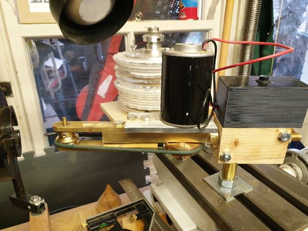
- Building a Universal Cutting Frame was a bit of a challenge. In the end I machined it out of a brass bar and used a small motor to drive it from a single pulley. The cutting bit is HSS drill bit ground to a rounded profile and mounted in a brass pulley.
- The electronics were easy for me because I have always enjoyed messing about with electrical gadgets and computers. Others may find it more challenging but there is lots of help available on YouTube, especially Gary Liming's website.
- Bill Ooms and Jon Magill were very helpful in pointing me in the right direction on many issues.
- Pat Miller's YouTube Video on the Spirograph attachment was very influential in the final design.
- I cannot remember what gave me the idea to try a laser engraver instead of a milling cutter but now I use it a lot, especially for Spirograph designs. I have messed about with 3 laser heads:
- 500 milliwatts (mW) is not powerful enough
- 2,500 mW is too aggressive
- 1,000 mW seems fine
- This YouTube Video show his engraver in action.
- The electronics are not difficult but soldering in some large press switches makes using them easier and you can hide the laser electronics in a small box.
- I had so much fun building the first RE that when we changed our bed and threw out the old one, I decided that the box section steel frame would make an ideal bed for a lighter, more portable machine that I can use for demonstrations. At the same time I acquired a 3D printer and used that to print out quite a few parts including:
- Rosettes
- Clutch plates
- Bearing housing
- Tool rest rubber mounts
- Building and tuning the RE is only the start! After 3 months with a finished machine that I am only just beginning to get to grips with what it can do.
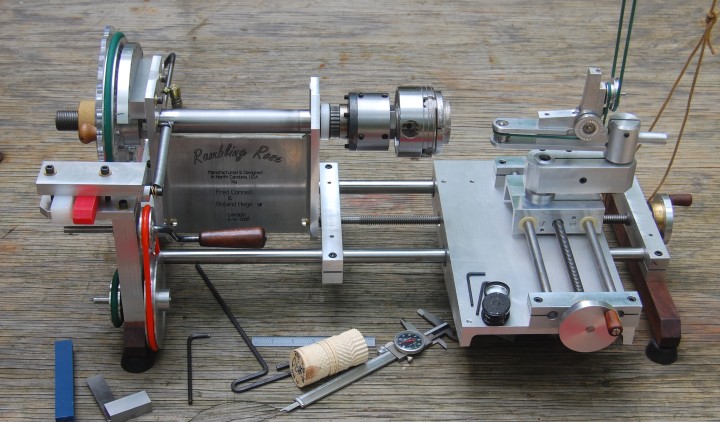
Rambling Rose Portable Rose Engine Lathe
Image courtesy Fred Connell
(and the late Roland Hege)
The Rambling Rose
Roland Hege and Fred Connell designed and built the Rambling Rose specifically to use in demonstrations. They had a list of 10 or so specific, design criteria that constrained their design; things such as it needed to weigh less than 50 pounds in its wooden shipping container.
Roland and Fred published their story and engineering plans for anyone to use to build their own non-commercial rose engine at OrnamentalRoseEngine.com. Fred noted to me that a fair level of metal working skills are required to build a "Rambling Rose" design.
Please do note that this is meant to be a portable machine for demos. So, if you are seeking something more permanent, you should look at a different, more robust design.
Fred also noted that, in his quest to learn about rose engines, many people helped him. As a give back, he created the OrnamentalRoseEngine.com website as a reference. He have never wanted to commercialize it and he tries to answer the questions it generates.
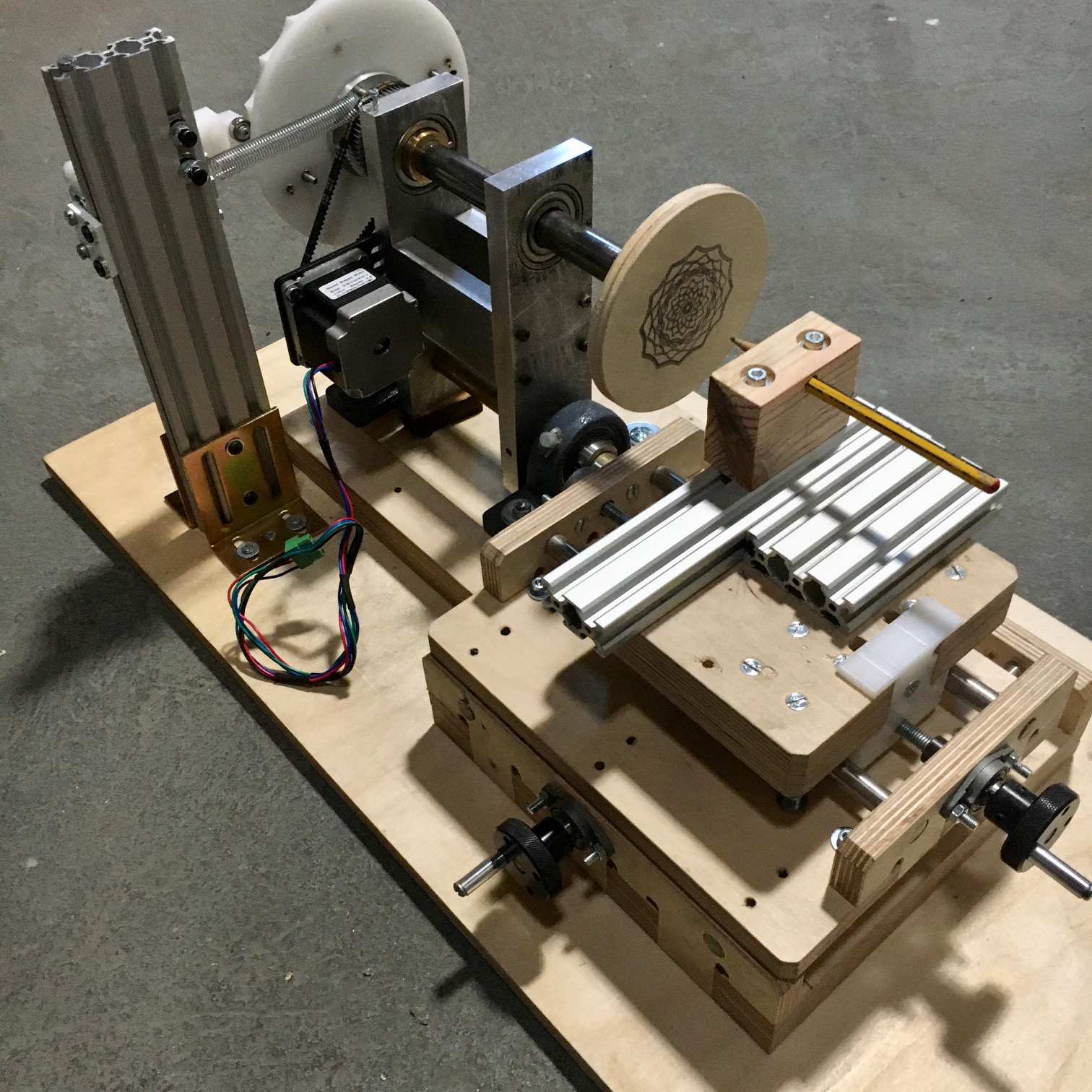
Jean-Michel Chartiel's Rose Engine Lathe
Jean-Michel Chartiel's Rose Engine Lathe
Jean-Michel contacted me in August 2020. I've paraphrased his note below:
|
Dear Rich, I am new to ornamental turning. I am an architect living in Portugal and most of the time I build some kind of machines (you can check my Instagram: atelier.pli). I found your website amazingly inspirational and it helped me a lot building my simple rose engine lathe. So I was wondering if you think that my machine could be of any help to anyone. If so I can share the cad and 3d files for the machine with pleasure. Here are a couple of pictures. I thought that maybe the cheap XY table or the fly cutter could be of interest? |
I really hoped that this site would help those new to OT to get started. And I believe Jean-Michel has been able to truly absorb the ideas of a rose engine lathe. Jean-Michel's machine has some really neat features of note:
- His cross slide seems to be made using standard, off-the-shelf parts used for 3D printers. These can be obtained from Amazon or other sources at a very good cost.
- His cross slide is made using plywood. This can really keep the cost down over buying one.
- The headstock pivot points are pillow blocks that can also be obtained from Amazon or other sources at a very good cost.
- He drives the spindle with a stepper motor. This is a great way to run it at slow speeds without losing torque. I'd be interested in knowing how he controls it. He is possibly using a controller/driver like the Tic 36v4 from Pololu.
|
Update from Jean-Michel For the stepper motor, I used the amazing article by snailwork at www.liming.org. He built an electronic indexing head. Works really nicely and is quite simple to make. |
If you are interested, please contact me and I will let Jean-Michel know you are interested.
|
Disclaimer: eMail comments to me at OTBookOfKnowledge @ Gmail.com. The process of woodturning involves the use of tools, machinery and materials which could cause injury or be a health hazard unless proper precautions are taken, including the wearing of appropriate protective equipment. |