Rosette Phaser / Multiplier
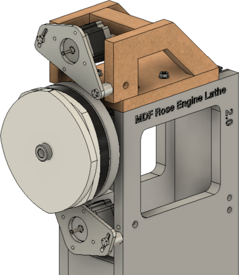
Rosette Phaser / Multiplier Installed on
an MDF Rose Engine Lathe
Tom Johanson came up with the idea of adding a second drive motor to the MDF Rose Engine Lathe, letting it drive the rotation of the rosettes. By doing this, the spindle drive motor is no longer driving the rosette rotation; only the rotation of the object being turned.
Ed French then added the functionality to use this in version 3.0 of the Control System for Multiple Stepper Motors (more information about that system is available at the MDF Rose Engine Lathe 2.0 Library).
Together, these deliver these functions for the turner:
- dynamic phasing of the rosette,
- multiplication of the rosette's patterns, and
- indexing of the rosette, separate from the object held in the spindle (as done using the worm screw on a crossing wheel).
Dynamic Rosette Phasing
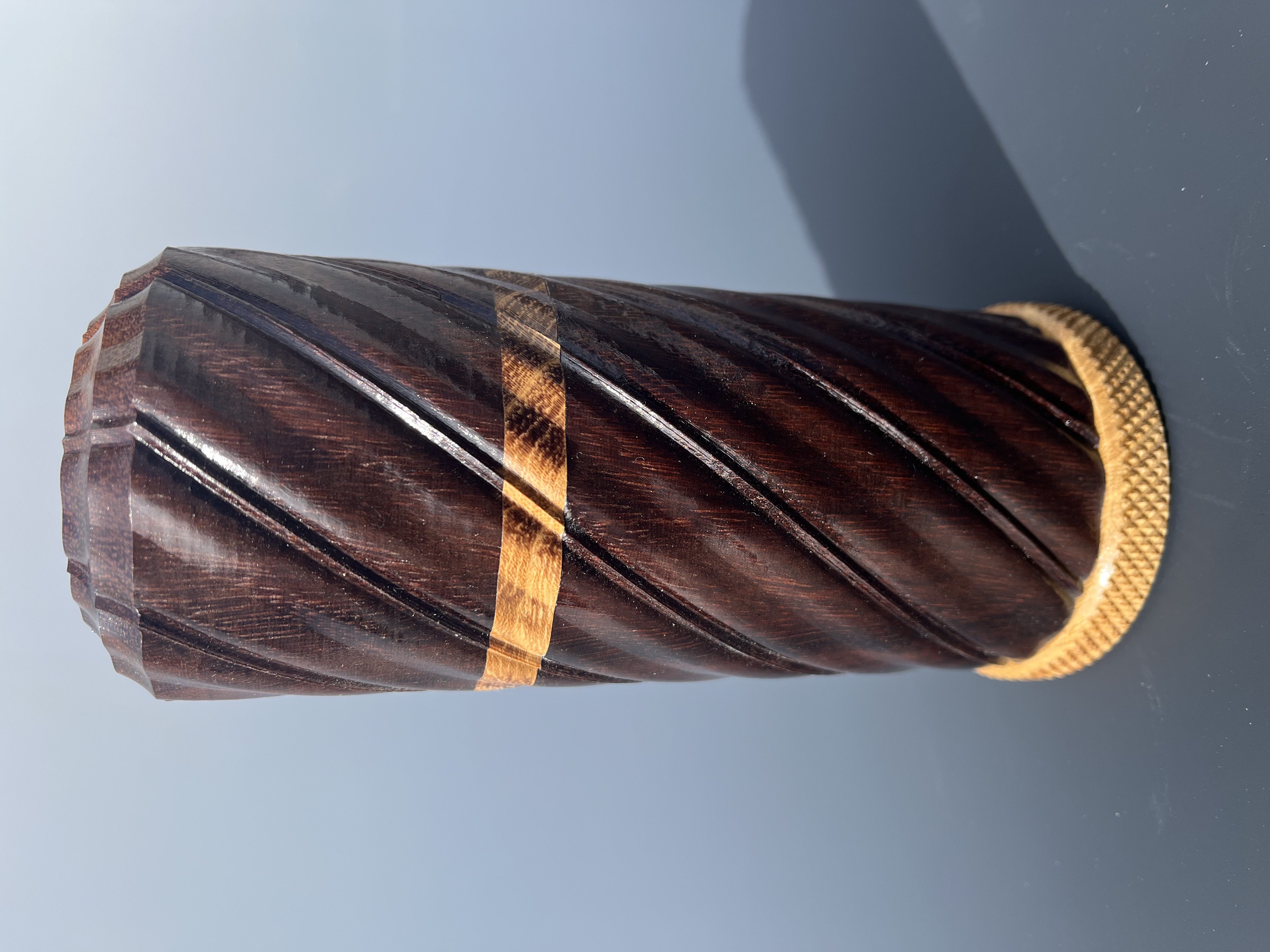
Tudor-8 pattern wrapped
180° around a cylinder
With the historical way in which phasing has been implemented, a series of cuts would be made, and then the rosette would be rotated (phased) relative to the object being cut. This certainly enabled some wonderful artistic effects.
With dynamic phasing, there is no need to stop the cutting before phasing.
An example of where this function would be useful is when cutting along the side of a piece using a linear or curvilinear slide. As the cutter is moved along the piece, the rosette can be phased dynamically. The effect would be to impart the rosette's design helically along the object, similar to screw threads.
The piece shown to the right shows such a pattern of rosette rotation.
Rosette Pattern Multiplication

Oval Rosette
By rotating the rosette at a different speed from the object, the rosette's pattern will be repeated more or less often. For example, if the rosette is rotating at twice the speed of the object, then the effect will be the same as having twice the patterns on the rosette.
The picture to the right shows an oval rosette with three multiplication factors, all using the same starting point.
- The black line is at 100% (i.e., no multiplication).
- The red line is at 50%. At 50%, there is only one lobe on the oval, making it rather circular.
- The blue line is at 200%. At 200%, there are four lobes. This looks like two oval rosettes were overlaid at 90° to each other.
Below are some examples using an F-4 rosette:
|
Actual Rosette = F-4 |
 |
Actual Rosette = F-4 |
 |
|
Actual Rosette = F-4 |
 |
Actual Rosette = F-4 |
 |
|
Actual Rosette = F-4 |
 |
Actual Rosette = F-4 |
 |
This opens up opportunities for the turner to have access to previously unavailable rosettes.
|
Actual Rosette = GDP-3 |
 |
Actual Rosette = A-96 |
 |
|
Actual Rosette = GDP-3 |
 |
Actual Rosette = A-96 |
 |
|
Actual Rosette = GDP-3 |
 |
|
- With the GDP-3 running at 50%, it takes 2 revolutions to complete the pattern.
Rosettes with different lobe structures have different amplitudes. For example, an F1 at 400% is very different from an F4 at 100%.
|
Actual Rosette = F-4 |
|
Actual Rosette = F-1 |
 |
|
|
"Impossible" Rosettes

One-Lobed Rosette
Tom was able to demonstrate some really unique features using his One-Lobed Rosette. By running the rosette at 16x the speed of the spindle, the effective result was a rosette which looked like the pattern shown to the left.

16-Lobed Virtual Rosette
Such a pattern of rises and falls would be impossible for a rubber to follow, so this would be a rosette which would be "impossible" to use.
Rosette Indexing
If the turner wants to adjust the rotational alignment of the rosette to the object being turned, there are a number of ways to do that; however the approach here is easiest. The steps would be:
- Secure the object in the chuck, and ensure it is aligned properly along the Z axis.
- Ensure the cutter is properly aligned, especially along the Y axis.
- Rotate the spindle so that the object is set at the desired starting point for cuts.
- Index the rosette (relative to the object held in the spindle) so that it is also aligned with the starting point for cutting. This is the new functionality for the MDF Rose Engine Lathe, and is similar to what is provided by the worm screw on a crossing wheel.
- Begin cutting ...
An example of where this function would be quite useful is when adding ornamentation to a segmented or staved piece. The piece can be rotated so that the pattern imparted by the rosette would start wherever the turner wanted.
Examples of this device in use
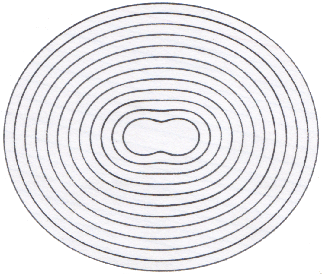
Oval Rosette
Tom Johanson did some testing surrounding the multiplication of the rosette's patterns. His tests were to try various options on the multiplication percentage when using an oval rosette. The oval rosette was chosen as its pattern collapses when the cut radius is small. This can be seen in the paper chuck drawing of an oval rosettes's pattern, shown to the right.
In this testing, the relationship of the rosette to the spindle's speed is reflected in the table below. All the drawings were made at a small diameter, with the same pen setting, and the same amplitude adjustment (100%).
What was found is that the percentage selection can drive an increase or decrease in the number of lobes (as noted above). Where there is an integer number of lobes, the results were shown in the table below on a row basis.
The columns in the table below, the number of revolutions, represents the full revolutions required to complete the pattern.
|
Revolutions | ||||||||
|
1 |
2 |
3 |
4 |
5 |
6 |
7 |
8 | |
|
1 |
 50% |
 25% |
 16.667% |
 12.5% |
 10% |
 8.333% |
 7.1429% |
 6.25% |
|
2 |
 100% |
n/a |
 33.333% |
n/a |
 20% |
n/a |
 14.286% |
n/a |
|
3 |
 150% |
 75% |
n/a |
 37.5% |
 30% |
n/a |
 21.429% |
 18.75% |
|
4 |
 200% |
n/a |
 66.67% |
n/a |
 40% |
n/a |
 28.571% |
n/a |
|
5 |
 250% |
 125% |
 83.333% |
 62.5% |
n/a |
 41.667% |
 35.714% |
 31.25% |
|
6 |
 300% |
n/a |
n/a |
n/a |
 60% |
n/a |
 42.857% |
n/a |
|
7 |
 350% |
 175% |
 116.667% |
 87.5% |
 70% |
 58.33% |
n/a |
 43.75% |
|
8 |
 400% |
n/a |
 133.33% |
n/a |
 80% |
n/a' |
 57.143% |
n/a |
|
9 |
 450% |
 225% |
n/a |
 112.5% |
 90% |
n/a |
 64.286% |
 56.23% |
|
10 |
 500% |
n/a |
 166.67% |
n/a |
n/a |
n/a |
 71.429% |
n/a |
To generalize what was found, for a given number of Lobes(L),
There are solutions also at harmonic values to this speed. So, for a given harmonic value (H),
What was also found is that the number of revolutions (R) required to complete the pattern equals the harmonic.
|
5 Lobes |
So, if you want 5 lobes with a design at the 3rd harmonic, the speed of M3 would need to be: |
|
Where there are blank cells in this table, there is no good solution. For example, there are desired solutions such as: | |
|
1 Lobe |
In theory that should work; however we also know that 50% yields a 1 Lobe object at the 1st harmonic. |
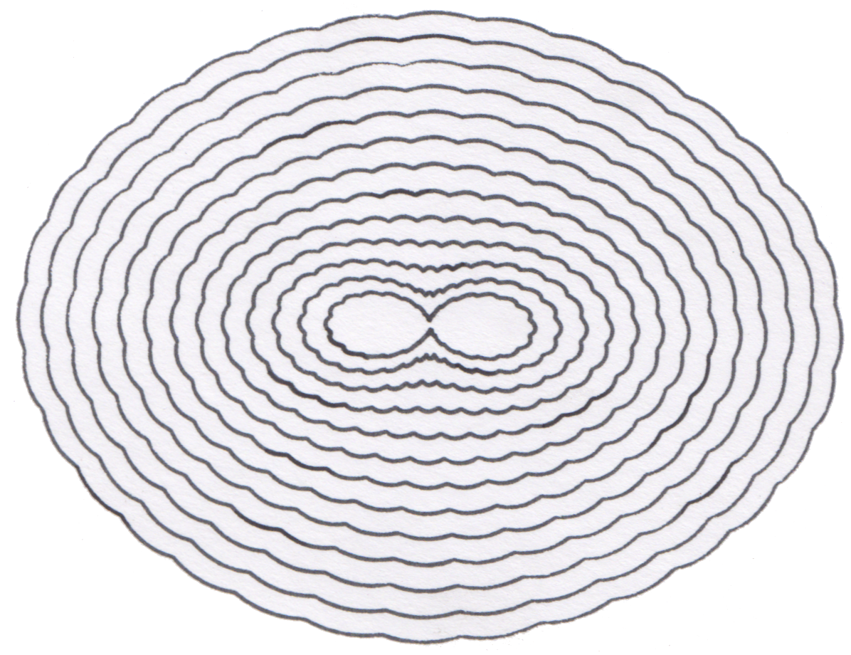
Bumpy Ellipse Rosette
Tom Johanson then ran a subset of this test again using the Bumpy Ellipse rosette.
What is greatly interesting here is how, at 11 and 12 revolutions, the bumps on the rosette become lobes in the design.
|
Revolutions | ||||||
|
1 |
2 |
3 |
4 |
5 |
6 | |
|
5 |
 250% |
 125% |
 83.33% |
 62.5% |
n/a |
 41.666% |
|
Revolutions | ||||||
|
7 |
8 |
9 |
10 |
11 |
12 | |
|
5 |
 35.714% |
 31.25% |
 27.777% |
n/a |
 22.727% |
 20.833% |
How it works
- This YouTube video overviews what it is, how it is attached to the rose engine lathe, and discusses how it works.
Notes on making one
The instructions for making one are in a manual at the MDF Rose Engine Lathe 2.0 Library. There is a red book there titled, Jigs, Fixtures, & Add-Ons.
|
Disclaimer: eMail comments to me at OTBookOfKnowledge @ Gmail.com. The process of woodturning involves the use of tools, machinery and materials which could cause injury or be a health hazard unless proper precautions are taken, including the wearing of appropriate protective equipment. |