Approaches for Implementing the Rose Engine Lathe's Movement
There are a number of approaches that could be taken to achieve ornamental turning. This page outlines the ones I know, and will probably trigger new ideas in the reader.
Index of Approaches
|
Object moves (rocks or pumps & rotates |
Cutter moves (rocks or pumps |
There are certainly exceptions to these, but these are good starting points for discussion.
Traditional Approach
The traditional approach to a rose engine is where the object rotates as on a traditional lathe, whilst also moving:
- back and forth, along the X axis (rocking),
- back and forth, along the Z axis (pumping), or
- both rocking and pumping.
To make these motions happen requires movement that would not happen easily on a traditional lathe.
Rocking requires the head stock to rock back and forth. In the traditional approach, the headstock is mounted on shaft that provides for the rocking motion.
- The upper shaft in the headstock is used to rotate the object.
- The lower shaft in the headstock is used to allow for the rocking motion.
Pumping is lateral movement of the upper shaft in the head stock whilst also rotating. This would be a problem if the shaft were held in bearings, so it is typically held in bushings, or the shaft may float on a layer of oil (e.g., journal bearings).
Whilst all that object movement is happening, a cutter, held in a cutting frame (or drill spindle) is cutting into the object. The cutting frame stays fixed, held in the quick change tool post on a [cross slide]].
This YouTube video shows all these things happening together.
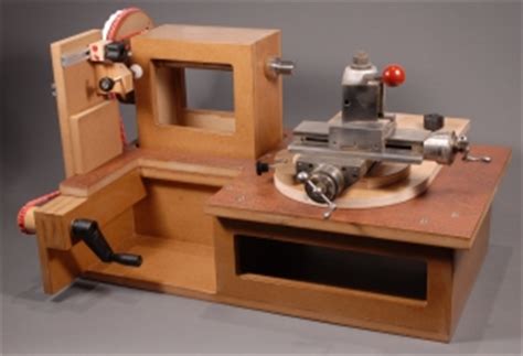
The MDF Rose Engine was designed by Jon Magill, and uses the traditional approach. The first designs did not make pumping motions; however I believe he has added that functionality in later designs. Others have also come up with designs to achieve this in different ways (see also, the YouTube video of Pat Miller's design).
|
Advantages |
Disadvantages |
|
|
Richard Coers' Approach
|
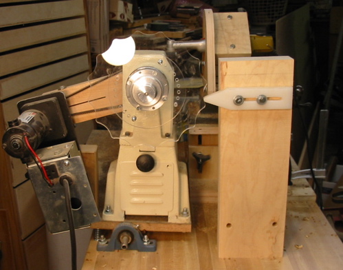
Richard Coers' Rose Engine Lathe Images courtesy Richard Coers |
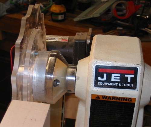
Richard Coers first showed an approach on the American Association of Woodturners' Forum where a smaller lathe (a midi lathe) is rocked. Fundamentally, the midi lathe becomes the headstock in an ornamental lathe.
Richard's approach is to mount a rosette on the outboard side of the midi lathe's headstock. Pictures of this approach are on the right.
I've not seen the work he makes with it (I think he does pen turning on it), but I do like the idea of reusing equipment that is otherwise unused. So I took that approach and flipped it around though.
My first rose engine lathe held the rosettes on a shaft between the headstock and tailstock, and the object was held in the outboard position (the headstock was rotated 180 degrees).
Videos of my first rose engine lathe in operation are below.
|
Advantages |
Disadvantages |
|
|
Update : I have abandoned this approach, and built an MDF rose engine lathe. There are a number of reasons, but suffice it to say, the user community for MDF lathes makes the change worthwhile.
Rod Tallack's Approach
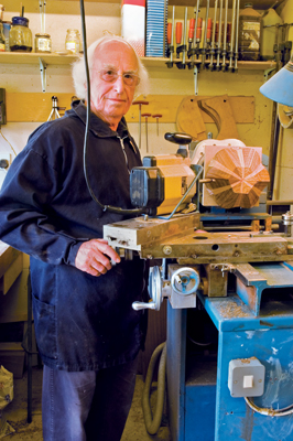
Mr. Tallack told me that ornamental turning just took too long to make a piece. So he designed a lathe that moves the object quite fast, whilst a router cuts the object.
He wrote a book about it titled, Woodturning : Another Dimension. Quite the read.
Rod had a YouTube video showing his lathe in action; however I cannot find it anymore. I watch this thing working and think, something must surely be falling apart soon. But, I've corresponded with him, and he assures me the machine is quite stable.
|
Advantages |
Disadvantages |
|
|
Paul Cler's Approach
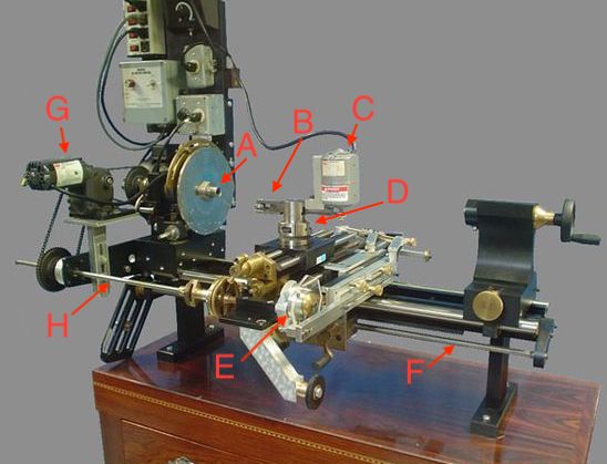
Paul Cler built a limited production lathe between 2000 and 2006 (shown in the picture to the right) which works on a different principle: namely the Geometric Slide-Rest, patented by Captain Richard Pudsey Dawson in 1870.
- The object is held in the rotating spindle (A) which can hold the object via a chuck mounted in the Morse taper or the threaded section.
- There is a chassis which handles the movement of the cutter.
- The direct drive (C) cutter in a horizontal cutting frame (B). (Note: a cutter could also be driven by an overhead drive.)
- The cutting frame (B) is held in a quick change tool post (QCTP - D)
- The QCTP is usually mounted on a cross slide.
- The cross slide is mounted to a platform which is attached to two sets of linear bearings (not well shown in this picture). These linear bearings enable movement of the platform in the X or Y axis (or both).
- The motor (G) that drives the spindle's rotational movement also drives a shaft (H) which rotates the rosette (E). The rosette's shape then drives the movement of the cross slide along the linear bearings.
- The motor (G) also drives a leadscrew (F). This leadscrew provides for driving the cutter's movement along the Z axis, like would be needed to use a curvilinear slide.
This approach greatly interests me.
- I believe a chassis can be made to fit on the bed of a traditional lathe, and this chassis can also use linear bearings to work like the one on the Paul Cler lathe for driving the action of the cutting frame.
- The lathe's spindle can also be outfitted with a stepper motor to make this happen, and to drive the lathe shaft's rotation (like the motor labeled with G, above does).
Jean Wiggins inherited a Cler lathe from her husband. In this YouTube video, she gives a tour of her shop and lathe, gives lessons learned in Ornamental Turning, and tells stories about various past projects.
This YouTube video from cbwim implements such Cler's approach. He used linear bearings for the movement along the X and Z axes. And he is rotating the spindle by hand. Turning the spindle without automation is typical for the guilloché he's doing.
This YouTube video from Lignolathe also implements such Cler's approach. That channel has a few other videos worth reviewing if you are going to pursue this path.
|
Advantages |
Disadvantages |
|
|
There is a good article where this approach was taken: Elementary Geometric Turning by Roger Malcomson and George Popplewell. The Society of Ornamental Turners Bulletin 146, Spring, 2022, pg. 5
Computer-Assisted Approach
|
Images courtesy Bill Ooms |
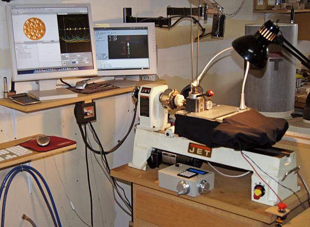
Bill Ooms and Dewey Garrett are also the leading pioneers in the use of computerization as an approach to ornamental turning. Both have YouTube channels with videos worth viewing:
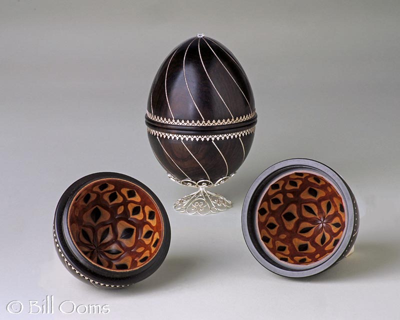
Bill and Dewey are very accomplished artists who have created great works. The piece that I consider to be Bill's most beautiful is shown to the right (he was very kind to share it). Dewey's work has been featured many places, and he has links to those on his web site.
In my correspondence with Bill, he has stated that he prefers the term "computer-assisted" over "CNC". His reasoning is that the use of a computer to help the artist achieve his goal is quite different from the typical use of computer numerical control (CNC).
CNC is often identified with the repeated production of given object, not one-off artistic work, but as noted in the video from Dewey, great artistic work can be done on a computer-driven lathe.
Bill documented the building of his Computerized Ornamental Lathe (COrnLathe™) on his web site. That site has a load of great information, and I won't take the time to repeat it here.
Bill is to be greatly commended for freely sharing three things :
- the COrnLathe™ "hardware" designs he has created,
- the software he has created, and
- the designs he has created for cutting frames.
These videos show Bill and Dewey's lathes in use:
Paul Paukstelis designed the LatheEngraver as a CNC-style system with the controls based around the very popular OctoPrint system used for years in 3D printing. This is currently available as an option for the ornamental turner wanting to pursue such an approach.
|
Advantages |
Disadvantages |
|
|
|
Disclaimer: eMail comments to me at OTBookOfKnowledge @ Gmail.com. The process of woodturning involves the use of tools, machinery and materials which could cause injury or be a health hazard unless proper precautions are taken, including the wearing of appropriate protective equipment. |


